Contrary to integrated circuits, the relays are discrete devices that give low-power logic signals a control over the higher power circuits. Sometimes, a relay will isolate the high power circuit and therefore assist in protecting the lower power circuit through providing the logic circuit with a small electromagnetic coil to control.
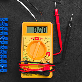
How are these relays tested on HVAC systems? Can it be done with a multimeter? Do I need any special knowledge to do so? If you’re looking for answers to these questions, read on – we’re here to help you out.
Starting Out
- The first thing you’ll have to do is to consult the relay schematic sheet. Most relays feature standard pin configurations, but checking out the schematic and finding out about the number of pins is always the best idea. In most cases, these will be printed on the relay itself.
- Information on pin configurations, voltage rating, current rating, and other info can be invaluable in testing, as it can easily eliminate the majority of errors that come with it. Of course, random testing without actually knowing anything about the pin configuration is entirely possible – however, with a damaged relay, the results can be quite unpredictable.
- Making a basic visual inspection should be your next step. Many models feature clear plastic shells that contain the contacts and the coil. Finding out visible damage, such as blackening or melting, can significantly help with narrowing down the problem.
- Luckily, most modern relays feature LED lights that tell the user if they’re in an active state. If this light isn’t working and you’ve got control voltage to the coil terminals or the relay, it’s pretty safe to conclude that the relay is bad.
- It goes without saying, but all electrical work should always be done only after the power sources have been disconnected, and this includes line voltage and batteries. One thing to be especially mindful of is the capacitors in the circuit – these are capable of holding the charge for quite some time after you’ve removed the power source.
- Another thing to consider here is checking the local laws before attempting to do any electrical work. In case you’re feeling unsafe, it’s best to leave this job to a professional.
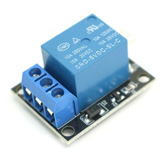
Testing a Coil Relay
- When testing a coil relay, make sure first to determine its coil requirements. Check out the manufacturer’s part number (listed on the case) and then take a look at the relevant datasheet and find out about the current and voltage requirements of the coil. Some relays will have this information printed on their cases, especially the larger models.
- The next thing you need to do is to find out about the control coil’s diode-protection. Some models will have diodes around the poles in order to safeguard the logic circuitry from the damage that occurs due to noise spikes. On drawings, these diodes are shown as triangles with bars across their corners. This bar will be connected to the positive connection, or the input, of the control coil.
- Next, you need to assess the relay’s configuration. As we said, this info can be found either on the case of the relay or on the manufacturer’s datasheet. Most models have one or more poles, and these are indicated by drawings with a single line switch that is connected to one of the relay’s pins.
- Each of the poles might have a NO (normally open) or an NC (normally closed) contact, and these will be indicated on the drawings. The drawings should show each pole as either touching (NC) or not touching (NO) the pin.
- The next step includes using a multimeter – you’ll have to test the de-energized condition of the contacts on the relay. Use the DMM (digital multimeter) to examine the resistance between the poles and their NO and NC contacts. All of the NO contacts should show infinite resistance and all NC contacts should show 0 ohms.
- Electrify the relay by using an independent voltage source which is suitable for the rating of the coils. Expect to hear a clicking sound when the relay is energized.
- Now that the relay is energized, you’ll be able to check the energized condition of its contacts. Take the multimeter and once again test the resistance between the poles and the NO and NC contacts. The NO contacts should read 0 ohms and the NC ones should read infinite resistance.
Testing a Solid-State Relay
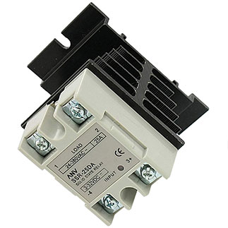
- When testing a solid-state relay, one has first to use an ohmmeter and check the relay across the NO (normally open) terminals once the control power is not working.
- Next, take a digital multimeter (DMM) and confirm the findings by using the device in its diode-test mode. The DMM will apply a tiny amount of voltage in order to make the semiconductor conduct, allowing you to read the voltage on display. In case the relay is bad, your multimeter will read OL or 0, and if it’s good, it’ll read 0.5 for a germanium transistor and 0.7 for a silicon transistor. The silicone transistors are a lot more common than the germanium ones.
- Most of the solid-state relays are quite cheap to replace and very easy to troubleshoot. However, they can last a long time when they’re kept cool. Typically, most models arrive in blocking mounts and DIN rail packages.
- One thing worth mentioning here is that there are also special relays called SCRs that are used for exquisite process temperature control. They come in two flavors – for IR lamps/ovens and for heating wires. In simple terms, these are fast switches on much faster switches that are capable of turning on and off, and they often fail because of the temperature fluctuations.
Even though it might sound complicated at first, testing an HVAC relay with a multimeter is actually an incredibly easy thing to do. By following the above-mentioned steps, you will quickly get the hang of the process and will be able to apply this knowledge in the future. Good luck!